
Number of concerns:99times
Product Type:Power Distribution
Shelf time:2024-12-18
Product description:The GSM lift wireless intercom call system product is the fifth generation of our company's products, the machine room with wireless GSM extensions to talk to the management centre, no wiring to reduce the daily use of maintenance costs, to provide a comprehensive intercom call solution for the management centre; adopt
Tel:400-879-0955
>Product Overview
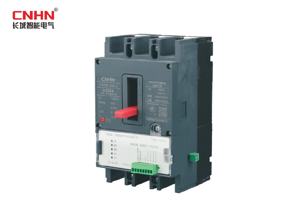
The measuring switches are suitable for use in three-phase, four-wire power distribution networks with a rated current of 100 A to 250 A and a rated operating voltage of 400 V, with direct grounding of the neutral point.
The Smart Energy Switch is a combination of a measurement unit module and a circuit breaker. The module is hot-swappable and interchangeable, enabling high-precision measurement of power consumption, voltage, current, temperature and other data on distribution lines, as well as data storage, processing and HPLC communication. Our measurement unit module meets industry standards and supports a number of IoT sensing functions such as identification of the topology of low-voltage power supply lines, management of metering boxes, early warning of power theft, reporting of power outages, analysis and diagnosis of line losses and automatic fault diagnosis. The circuit breaker has three protection functions: long delay time for overload, short delay time for short circuit and instantaneous short circuit.
Product compliance with standards: see normative documents for details.
>Model number and meaning

>Product terminology
Current transformers
It is a detection device that converts the detected current information into an electrical signal that meets the needs of the standard according to a certain pattern, e.g. current transformer, Hall element, etc.
Measurement units
In conjunction with current transformers and low-voltage switches, it enables high-precision metering of voltage, current and temperature in distribution lines, with data storage, processing and communication functions, and supports hot-swapping and interchangeability.
Smart Energy Switch
Low-voltage switchgear with high-precision current sensors and measurement units, including plastic-enclosed circuit breakers and disconnectors, for normal connection, segmentation, overload and short-circuit protection of distribution lines and for local or remote interaction of measurement data, suitable for distribution lines with AC 50Hz, operating voltage up to 440V and rated current up to 800A, and for installation in low-voltage metering boxes, branch boxes and distribution cabinets.
Normative documents
Q/GDW 1374.3-2013 Technical Specification for Communication Units
Q/GDW 1379.4-2013 Technical specification for inspection of communication units
DL/T 698.45-2017 Electricity information collection and management system Part 4-5: Communication protocols - Object-oriented data exchange protocols
DL/T645 -2007 Multifunction meter communication protocol
GB/T 7261-2016 Basic test methods for relay protection and safety automation devices
GB/T 14048.1 Low-voltage switchgear and controlgear Part 1: General provisions
GB/T 14048.2 Low-voltage switchgear and controlgear Part 2: Circuit breakers
GB/T 14048.3 Low-voltage switchgear and controlgear Part 3: Switchgear, disconnectors, isolating switches and fuse assemblies
GB/T 13729-2019 Telematic terminal equipment
GB/T 17626.18-2016 Electromagnetic compatibility Testing and measurement techniques Damped oscillatory wave immunity test
GB 4208-2008 Enclosure protection class (IP code)
GB/T 5169.11-2006 Fire hazard test for electrotechnical products
GB/T 16935.1-2008 Insulation fits of equipment in low-voltage systems Part 1: Principles, requirements and tests
Q/GDW 10354-2020 Functional specification for three-phase intelligent energy meters
Q/GDW 10365-2020 Type specification for three-phase intelligent energy meters
Q/GDW 11421-2020 Technical Specification for External Circuit Breakers for Electricity Meters
GB/T 17626.1 General introduction to immunity tests for electromagnetic compatibility testing and measurement techniques
GB/T 17626.4 Immunity test for electrical fast transient bursts
GB/T 17626.5 Surge (shock) immunity test
GB/T 17626.8 Immunity test for working frequency magnetic fields
>Form and mounting dimensions

Table 1-1 Description of the technical parameters of the measurement unit module

Table 1-2 Description of the technical parameters of the Smart Energy Switch
>Products

Table 2-1 List of main functions of the Smart Energy Measurement Switch
Smart Energy Switch Form and Mounting Dimensions(Unit: mm)

Installation instructions
1、The Smart Energy switch should be mounted vertically and secured with screws through the mounting holes.
2、Before installation, it is important to check that the Wise Energy test switch is in the split position.
3、The user selects the appropriate conductor according to the load and connects the main circuit conductor to the Smart Energy Switch (copper connector must be connected). The upper terminal of the Smart Energy Switch is the power terminal of the main circuit and the lower terminal is the outlet terminal. The neutral wire (zero wire) must be connected to the "N" terminal on the right side of the switch. The terminal fixing screws must be tightened and torqued to national standards.
4、After installation and wiring as specified, the Smart Energy switch can be powered up.
Table 2-1 List of main functions of the Smart Energy Measurement Switch

Figure 2-2 Schematic diagram of the external dimensions of the measurement unit module (general purpose)
Installation instructions
1、(a) With the measurement unit module facing upwards, insert the strong and weak power pins into the Smart Energy Switch in a direction perpendicular to the positive tangent of the Smart Energy Switch;
2、The pins of the strong and weak electrical interfaces, respectively, are aligned with the corresponding sockets of the Smart Energy measurement switch and ensure reliable connection;
3、When the module is installed and the Smart Energy switch is energised, the operating light above the module flashes to indicate that the module is working correctly.
2.3.2.3 External interfaces
The external interface of the measurement unit module uses 3.5mm pitch 8-pole pluggable terminals; the external interface terminals are located on the front of the module, please refer to Figure 2-5 for the interface arrangement and connection method, please refer to Table 2-4 for the specific pin definition (Note: the interface sequence corresponds to the main view in the dimensional drawing of Figure 2-2).

Figure 2-5 Diagram of the external interface of the measurement unit

Table 2-4 Definition of external interface terminals of the measurement unit module
2.3.3 Indicator lights
The measurement unit module indicators are located on the front panel of the module as shown in Figure 2-6 and the LEDs meanings are shown in Table 2-5.

Figure 2-6 Front view of the measurement unit module

Table 2-5 Definition of indicators for measurement unit modules