
Number of concerns:99times
Product Type:Power Distribution
Shelf time:2024-12-18
Product description:The GSM lift wireless intercom call system product is the fifth generation of our company's products, the machine room with wireless GSM extensions to talk to the management centre, no wiring to reduce the daily use of maintenance costs, to provide a comprehensive intercom call solution for the management centre; adopt
Tel:400-879-0955
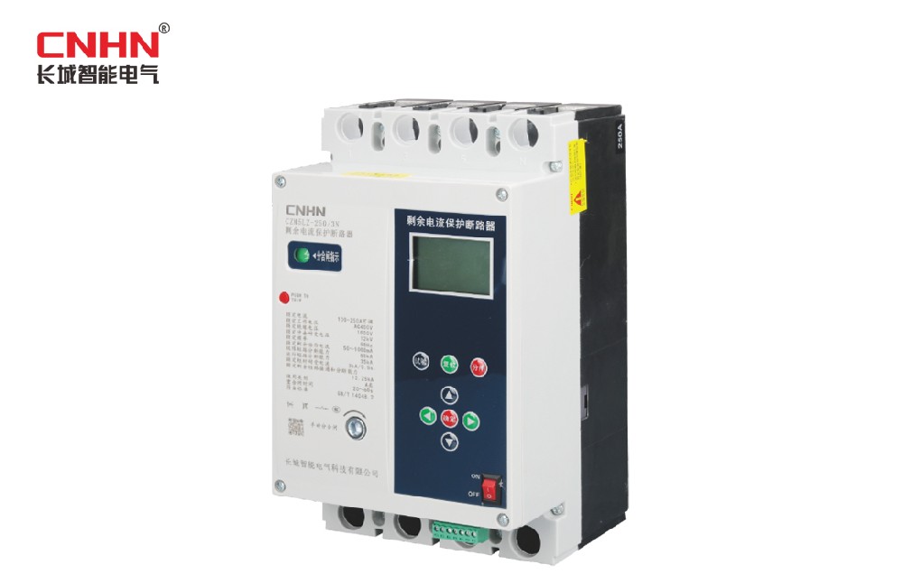
>Product Overview
CZM5LZ series residual current circuit breaker (hereinafter referred to as circuit breaker) is a circuit breaker integrating residual current relay, contactor and plastic case circuit breaker, which is suitable for three-phase four-wire neutral point grounded power supply and consumption system to protect the line or power equipment from ground fault, over current, short circuit, phase failure and over voltage. They can also be used to prevent electrical fires and damage to electrical equipment caused by ground faults in electrical lines or electrical equipment and to provide indirect contact protection against the risk of personal electric shock.
The circuit breaker overcurrent decoupler is electronic and the rated current of the circuit breaker is adjustable according to the line load. The three-stage protection curve is adjustable and can be used in conjunction with lower level circuit breakers to achieve graded protection. The electronic overcurrent detriggers have high protection accuracy and are less affected by the ambient temperature and installation position, and are an upgrade of the thermal magnetic overcurrent detriggers.
The circuit breaker is equipped with an RS485 serial interface, which allows the protection characteristics to be set via a programmer and to meet the requirements of the communication network.
Products conform to the standards: GB/T14048.2, GB/T22387.
>Model number and meaning

>Normal working conditions
● Ambient temperature -5°C to +55°C;
● Where the average minimum temperature of the wettest month of relative air humidity does not exceed 25 °C, the average monthly maximum relative humidity for that month does not exceed 90%, taking into account condensation occurring on the surface of the product as a result of temperature changes;
● Altitude not exceeding 2000 metres;
● Pollution level 3;
● Installation category III;
● The external magnetic field of the installation site does not exceed 5 times the geomagnetic field in any direction.
>Product features
Protection function:
● With residual current alarm, automatic gearing and sudden change, special wave, automatic closing, power-on test closing function; over-voltage, under-voltage, phase break protection, full loss of voltage function, and detection of voltage back to normal automatically re-close; electronic type also has overload, short circuit short delay and instantaneous protection; lack of zero protection, over-current unbalance and other functions.
Display functions:
● In the closed state, the current rated residual current action value, rated current value, current time, and maximum leakage value and phase, current three-phase voltage parameters, current three-phase current parameters, etc. are automatically displayed in turn.
Setup, enquiry function:
● Residual current alarm, auto-tracking, sudden change, special wave, auto-reclosing, overvoltage, undervoltage, phase loss, overload and zero loss protection can be enabled and disabled via the keypad. The above functions can also be set via communication. The alarm enabling and disabling functions of the operating data can only be set via the communication interface.
● The main parameters such as rated residual current, rated limit non-drive time, rated current, short-circuit short delay time, short-circuit short delay time, short-circuit instantaneous multiplier, timed test jump time, real time clock and user password can be set via the keys.
● The trip record, test record, total number of trips, number of latching trips, and many other parameters can be queried by pressing the key.
Control functions:
● Field test trip control is possible via the test button.
● Remote appointment for tripping, closing and test trips, and appointment for cancellation of control functions.
● Synchronous breaking and closing of the protector can be achieved by means of an external break and reset interface.
Self-test function:
● Three self-test functions are available: remote test jump, timed test jump, and key test jump.
Monitoring and recording functions:
● Record the residual current, three-phase voltage, daily maximum and hourly scale, minimum and time of three-phase current for a period of 30 days, for a total of 14 records.
● Record the residual current, three-phase voltage, three-phase current parameters and time for the last 10 trips.
● Recording of the last 10 residual current alarm (strong send) events, events of the protector's self-test, and residual current overrun events, for a total of 3 records.
● Total number of protector trips, number of latching trips, number of residual current trips and 6 other cumulative parameters.
Auxiliary functions:
● Rs485 communication function, in line with the requirements of the Technical Specification for Residual Current Action Protectors issued by Zhejiang Province.
● Residual current over limit alarm function.
● High brightness LCD screen, and 8 keys for parameter setting, parameter calibration, system restart, data query, key test, gate splitting and other field operations.
>Controller key performance indicators

>Actuation performance of the decoupler
Overload protection characteristics (inverse time action)

Calculation of the long overload delay time: T1 = (6Ir1/I)² x Tr1 (Ir1: rated current, I: is the actual applied current, Tr1: is the time factor)
Instantaneous overcurrent decoupler current setting value

Description of external terminals
External terminals:
1,2 pins for RS485 communication interface; 3 pins for breaking, 4,5 pins for reset function; short connection 3,4 pins, the circuit breaker tripped and latching, short connection 4,5 pins, the circuit breaker automatically re-closing; the remaining 6,7 pins connected to the main board JP7 seat (can be used for other purposes). External terminals as shown in the figure

>Installation and external dimensions

>Functional classification

注:● indicates that the function is standard, □ indicates that the function is optional
Protective features
Overload long delay protection

Time delay characteristics
Overload protection according to inverse time limit:
T=(6Ir1/I)²×Tr1, ±20%; T is the actual action time; I is the fault current; Tr1 is the delayed rectification value; Ir1 is the action rectification value.
Short-circuit delay protection

Time delay protection
Overload long delay protection

Time delay characteristics
Overload protection according to inverse time limit:
T=(8Ir1/I)²×Tr2 and T>200ms (less than 200ms according to 200ms delayed action), ±20%;
T is the actual operating time; I is the fault current; Tr2 is the delayed rectification value; Ir1 is the operating rectification value.

Residual current protection characteristics
Range of gear settings

Movement characteristics

Automatic reclosing
When the residual current exceeds the action current value gear action tripped, after 20-60 seconds of time can automatically re-close, but the manual closing is not limited by time. If the fault current is eliminated within 3 minutes after closing, the circuit breaker is closed successfully and the circuit breaker operates normally; if the fault current is not eliminated, the circuit breaker trips again and locks, it will not automatically re-close and must be manually operated to close the circuit breaker.
Protection functions
Overvoltage protection function
When the line phase voltage is higher than the set value, the circuit breaker protection trips after a 5-second delay. When the line voltage returns to normal voltage, the circuit breaker can be automatically closed and put into operation. The set value of overvoltage protection ranges from 220-350V in steps of 1V; the user can also set the protection on or off by himself.
Undervoltage protection function
When the line phase voltage is lower than the set value, the circuit breaker protection trips after a 5-second delay. When the line voltage returns to normal voltage, the circuit breaker can be automatically closed and put into operation. Under-voltage protection is set in the range of 150-220V, step: 1V; users can also set their own protection to open or disable.
Phase loss protection function
When the line is out of phase at the power end of the line, the circuit breaker protection trips. When the line voltage returns to normal voltage, the circuit breaker re-closes. The set value of phase loss protection ranges from 80-150V, step: 1V; users can also set their own protection to open or disable.
>Installation and first use
● The circuit breaker should be mounted vertically and secured with screws through the mounting holes.
● The user selects a suitable conductor according to the load and connects the conductor to the circuit breaker (copper connectors must be connected). The upper terminal of the circuit breaker (1, 3, 5, N) is the power inlet terminal of the main circuit, and the lower terminal is the outlet terminal. The neutral wire (zero wire) of the power supply must be connected to the "N" terminal.
● After installation, confirm that the boat switch is in ON state, then power the circuit breaker. If the green indicator light is on, the LCD screen shows "try to close in", indicating that the circuit breaker is in a split state, then the circuit breaker will automatically close, after 20-60 seconds of normal closing, the green indicator light flashes, indicating successful closing, the LCD screen wheel shows the current parameters. Red indicator light is always on, indicating that the protector tripped and blocked, press the [reset] key to make the protector enter the automatic re-closing state.
>Cautions
● After the earth leakage circuit breaker has been put into normal operation, it should be tested and tripped once a month and recorded;
● Not to use the phase to neutral short circuit to test the trip, so as not to cause a short-circuit current and burn the device, in which a resistor of about 1KΩ should be connected in series (determined according to the regulations);
● No protection against the risk of electric shock caused by simultaneous contact with both wires of the circuit being protected;
● The circuit breaker must not be opened without permission, otherwise you will be responsible for the consequences.
● According to the national and industry residual current action protector rural installation and operation regulations (DL/T736-2000), for disconnection of the power supply will cause accidents or major life, economic loss of emergency, by the power supply enterprises approved by the technical department in charge of the residual current protector will be temporarily withdrawn from operation, the protection period will be set to residual current alarm mode. After entering the alarm state (the alarm indicator light is always on), the protector loses the residual current protection function. After the emergency state is lifted, the protector must be put back into operation and cannot be used for a long time without reason.